Level Control
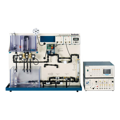
In this experiment, students learn to apply control design techniques on a liquid level process system to control the liquid level in a holding tank. This liquid level process system consists of a reservoir (as seen in the lower left hand corner of the below figure), a holding tank (directly above the reservoir), a piping channel (middle to lower right hand side of below figure), a fixed voltage water pump (not seen in figure), and a servo valve (center of below figure).
In operation, the liquid level process system pumps liquid from the reservoir into a piping channel . In an intermediate location along this piping channel, liquid passes through a servo valve, which controls the flow rate pumping into a holding tank. In addition, liquid exits the holding tank by means of a constant diameter exiting orifice (located at the bottom of the holding tank).
The objective of this experiment is to design a proportional-plus-integral controller that makes the liquid level in the holding tank track a desired setpoint level.
